Unit 1: Introduction to Microprocessors
Fundamentals of microprocessors, their history, and basic concepts
Definition and History of Microprocessors
Definition of a Microprocessor
A microprocessor is a single integrated circuit (IC) that incorporates the core functions of a computer's central processing unit (CPU).
-
The "Brain" of a Computer: It executes instructions, performs calculations, and manages the flow of data within a computer system.
-
Small and Powerful: Microprocessors pack millions or even billions of transistors into a tiny chip, enabling complex processing in compact devices.
-
Essential for Modern Devices: They power a vast range of devices from smartphones and laptops to cars, appliances, and industrial equipment.
-
Components: Typical components of a microprocessor include:
- Arithmetic Logic Unit (ALU) - Performs arithmetic and logical operations
- Control Unit (CU) - Decodes instructions and coordinates the operations of other units
- Registers - Small, high-speed memory locations for temporary data storage
-
Responsible for:
- Fetching instructions: Retrieving instructions from the computer's memory.
- Decoding instructions: Translating instructions into a form the microprocessor understands.
- Executing instructions: Performing calculations and logical operations based on the instructions.
- Controlling data flow: Managing the movement of data between memory, input devices, output devices, and the microprocessor itself.
History
The evolution of microprocessors is a fascinating story of technological advancement:
- Early Computers (1940s-1950s): The first computers were massive, filling entire rooms. They used vacuum tubes for processing, which were bulky, power-hungry, and prone to failure.
- Transistors (1950s-1960s): The invention of the transistor revolutionized electronics. Transistors were smaller, faster, and more reliable than vacuum tubes, leading to smaller and more powerful computers.
- Integrated Circuits (1960s): Integrated circuits (ICs) combined multiple transistors, resistors, and other components onto a single chip. This enabled further miniaturization of computers.
- The First Microprocessor (1971): Intel released the Intel 4004, the first commercially available microprocessor on a single chip. While limited in power by today's standards, it paved the way for the computing revolution.
- Rapid Advancement (1970s-1980s): This period saw exponential growth in microprocessor performance with the introduction of iconic processors like the Intel 8080, Zilog Z80, and Motorola 6800. These processors found their way into the first personal computers.
- Modern Era (1990s-Present): Microprocessors have become incredibly powerful, with billions of transistors on a single chip. They power not only our computers but also smartphones, tablets, smart devices, cars, and countless other technologies.
Key milestones in microprocessor history:
- 1971: Intel 4004 (4-bit)
- 1974: Intel 8080 (8-bit)
- 1978: Intel 8086 (16-bit) - foundation of the x86 architecture used in many PCs today.
- 1993: Intel Pentium (32-bit) – brought significant performance gains
- 2000s: Introduction of multi-core processors
- Present: Continued focus on performance, power efficiency, and specialized microprocessors for tasks like AI and machine learning.
Basic Components of a Digital Computer
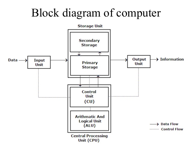
A digital computer is a versatile device capable of performing calculations and logical operations at incredible speeds. To achieve this, a computer relies on several fundamental components working together:
-
Input Unit: This unit bridges the gap between the user and the computer. It allows data and instructions to be entered into the system. Some common input devices include:
- Keyboard
- Mouse
- Touchscreen
- Scanner
- Microphone
-
Storage Unit: The storage unit preserves data, instructions, and results for short-term and long-term use. It's divided into two main categories:
-
Primary Storage (Main Memory): This fast, but relatively expensive memory temporarily holds the currently running programs, input data, and intermediate calculations. Since primary storage is volatile, data is lost when the computer powers down. RAM (Random Access Memory) is the most common type of primary storage.
-
Secondary Storage (Auxiliary Memory):
This type of storage acts as a permanent repository for programs, data, and the operating system. It's slower than primary storage but offers larger capacity at a lower cost. Examples include:
- Hard Disk Drives (HDD)
- Solid-State Drives (SSD)
- Optical Disks (CDs, DVDs)
-
-
Central Processing Unit (CPU): The CPU is the "brain" of the computer responsible for controlling and executing instructions. It contains two primary parts:
- Control Unit (CU): The orchestrator of the CPU. It fetches instructions from memory, decodes them, and generates signals to coordinate the activities of the other components within the system.
- Arithmetic Logic Unit (ALU): The heart of calculations. The ALU performs arithmetic operations (addition, subtraction, etc.) and logical operations (AND, OR, NOT, etc.).
-
Output Unit: The output unit presents the results of processing to the user in a human-readable form. Examples include:
- Monitor (display)
- Printer
- Speakers
How These Components Work Together
- Input: A user enters data or instructions through an input device like a keyboard or mouse.
- Storage: Data and instructions are temporarily stored in the main memory (RAM) for quick access by the CPU.
- Processing:
- The Control Unit fetches an instruction from memory and decodes it.
- The ALU executes the instruction, potentially involving calculations or logical comparisons.
- Results might be stored back into memory (RAM or secondary storage).
- Output: The processed results are presented to the user through an output device, such as a monitor or printer.
Basic Components of a Microprocessor
CPU (Central Processing Unit)
- The Brain: The CPU is the heart of a microprocessor, responsible for interpreting and executing instructions. Think of it as the decision-maker and coordinator of the entire system.
- Key Components:
- Control Unit (CU): The manager that fetches instructions from memory, decodes them, and controls the flow of data and operations throughout the processor.
- Arithmetic Logic Unit (ALU): The "calculator" within the CPU that performs all arithmetic (addition, subtraction, etc.) and logical (AND, OR, NOT, etc.) operations.
ALU (Arithmetic and Logic Unit)
- The Calculator: The ALU is a core part of the CPU, dedicated to carrying out the calculations and logic comparisons that drive computations within the microprocessor.
- Operations:
- Arithmetic: Addition, subtraction, multiplication, division, etc.
- Logical: AND, OR, XOR, NOT, comparisons, etc.
Control Unit
- The Orchestrator: The control unit is another essential part of the CPU. It directs all operations within the microprocessor.
- Responsibilities:
- Instruction Fetching: Retrieves instructions from memory.
- Instruction Decoding: Interprets instructions to determine what needs to be done.
- Control Signals: Generates signals to coordinate the ALU, memory, and other components, ensuring everything works in sync.
Memory Unit (RAM, ROM)
- Data and Code Storage: The memory unit is where the microprocessor stores important data and instructions.
- Types:
- RAM (Random Access Memory): Temporary, fast storage used for currently running programs and data. It's volatile, meaning data disappears when the power goes off.
- ROM (Read-Only Memory): Permanent storage that typically holds the computer's startup instructions (BIOS) and other essential data that shouldn't change.
Input/Output (I/O) Units
- Communication Bridge: These units facilitate communication between the microprocessor and the outside world.
- Input Devices:
- Keyboard
- Mouse
- Scanner
- Microphone
- Network interface card
- Output Devices:
- Monitor
- Printer
- Speakers
- Network interface card
How It All Works Together
- Fetch: The Control Unit fetches an instruction from memory (RAM).
- Decode: The Control Unit decodes the instruction to figure out the required operation.
- Execute:
- If it's a calculation or logical operation, the ALU gets involved.
- Data may be moved between memory, the ALU, and internal registers (tiny, super-fast memory within the CPU).
- Store: Results might be written back to memory or sent to an output device.
Architectures
Von Neumann Architecture
- Key Features:
- Single Unified Memory: Both instructions and data reside in the same memory space.
- Single Bus: A shared bus is used for transferring both data and instructions.
- Sequential Execution: Instructions are fetched and executed one at a time.
- Components:
- Central Processing Unit (CPU) with Control Unit (CU) & Arithmetic Logic Unit (ALU)
- Unified Memory
- Input/Output (I/O) devices
- Bus
- Advantages:
- Simplicity: Easier to design and implement.
- Flexibility: Programs can modify their own code, enabling dynamic behavior.
- Limitations:
- The von Neumann Bottleneck: Limited bandwidth due to the shared data and instruction bus, potentially slowing down processing.
- Security Concerns: Less separation between code and data can increase vulnerability to some types of cyber-attacks.
Harvard Architecture
- Key Features:
- Separate Memories: Distinct memory units for instructions and data.
- Dedicated Buses: Separate buses for fetching instructions and accessing data.
- Parallel Execution: The CPU can access instructions and data simultaneously.
- Components:
- Central Processing Unit (CPU) with Control Unit (CU) & Arithmetic Logic Unit (ALU)
- Separate instruction and data memory
- Dedicated buses for each memory
- Input/Output (I/O) devices
- Advantages:
- Speed and Efficiency: Parallel access offers faster execution and eliminates the bottleneck present in Von Neumann architectures.
- Enhanced Security: Improved isolation between code and data can aid security measures.
- Deterministic Behavior: Reliable timing and performance make it ideal for real-time systems.
- Limitations:
- Increased Complexity: More complex to design due to additional memory units and buses.
- Less Flexible for Self-Modifying Code: Separating code and data makes it more difficult for programs to modify their instructions on the fly.
Von Neumann vs Harvard Architecture
Similarities
- Fundamental Components: Both architectures include a CPU (with CU and ALU), memory, and I/O devices.
- Stored-Program Concept: Both can store programs in memory and execute them.
Differences Summary Table
| Feature | Von Neumann Architecture | Harvard Architecture |
|---|---|---|
| Memory Structure | Single unified memory for instructions and data | Separate memory spaces for instructions and data |
| Buses | Single bus for instructions and data | Separate, dedicated buses for instructions and data |
| Instruction Processing | Sequential | Potential for parallel instruction fetch and data access |
| Performance | Potential bottleneck due to shared bus | Faster, eliminates the bottleneck |
| Complexity | Simpler to design and implement | Increased hardware complexity |
| Flexibility | Programs can self-modify code | Less flexible for self-modifying code |
| Security | Less isolation between code and data | Improved isolation |
| Applications | General-purpose computers, laptops, servers. | Embedded systems, microcontrollers, digital signal processors (DSPs). |
| Diagram | 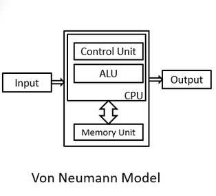 | 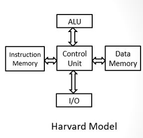 |
Table: Von Neumann vs Harvard Architecture
Instruction Formats & Related Terms
Instruction Format
A microprocessor instruction is a fundamental command encoded in binary that tells the microprocessor to perform a specific operation. Instructions generally have two core parts:
Opcode (Operation Code)
Specifies the operation the microprocessor should perform (e.g., add, subtract, move data, compare). The opcode is a unique binary pattern assigned to a particular action.
Operand
Data the operation acts upon. An operand could be:
- Immediate Value: Data directly included in the instruction itself.
- Register: A small, fast memory location inside the processor.
- Memory Address: A location in the main memory.
Example
Consider a simple 'ADD' instruction in a hypothetical microprocessor:
ADD R1, #5
- Opcode: 'ADD' tells the processor to perform an addition operation.
- Operands:
- 'R1' is a register, indicating one value for the addition is stored in register R1.
- '#5' is an immediate value, specifying the second value for the addition.
Instruction Cycle
The instruction cycle is the complete sequence of steps a microprocessor takes to process a single instruction. It involves:
-
Fetch: The Control Unit retrieves the instruction's opcode from memory.
-
Decode: The Control Unit decodes the opcode to understand the required operation.
-
Execute:
The instruction is carried out. This may involve:
- Reading data from memory or registers.
- Performing calculations or logical operations in the ALU.
- Writing results back to memory or registers.
Machine Cycle
A machine cycle represents a single, indivisible action performed by the microprocessor necessary to carry out part of an instruction's operation. Some examples of machine cycles include:
- Memory Read: Fetching data from memory.
- Memory Write: Storing data into memory.
- I/O Read: Reading data from an input device.
- I/O Write: Sending data to an output device.
An instruction cycle often comprises multiple machine cycles.
T-State (Clock Cycle)
A T-state is the fundamental unit of time in a microprocessor, measured by a single period of the processor's internal clock. Each machine cycle typically takes one or more T-states. Faster clocks mean more T-states per second, facilitating faster processing.
Relationship
- Instructions are built from opcodes and operands.
- An instruction cycle consists of the steps to execute one complete instruction.
- A machine cycle is a smaller unit of action within an instruction cycle.
- T-States are the fundamental timing unit, with a machine cycle usually encompassing multiple T-states.
Instructions in the 8085 microprocessor can be 1, 2, or 3 bytes long. The structure varies depending on the specific instruction and the addressing modes used.
RISC vs. CISC
| Feature | RISC (Reduced Instruction Set Computer) | CISC (Complex Instruction Set Computer) |
|---|---|---|
| Instruction Set | Smaller, simpler instructions. Focus on individual operations. | Larger, more complex instructions capable of multiple operations within a single command. |
| Addressing Modes | Limited addressing modes. | Extensive addressing modes for flexible data access. |
| Execution | Emphasizes hardware optimization. Instructions often execute in one clock cycle. | Utilizes microcode to implement complex instructions, potentially requiring multiple clock cycles per instruction. |
| Compiler Design | Relies on simpler instructions, shifting complexity to the compiler. | Simplifies compiler design by offloading complexity to processor hardware. |
| Memory Access | Load/Store architecture: Data must be explicitly moved between registers and memory for operations. | Instructions can operate directly on memory. |
| Pipelining | Highly efficient pipelining. | Pipelining can be less efficient due to variable-length instructions. |
| Register Usage | Large number of general-purpose registers for fast operand access. | Fewer registers, often with specialized purposes. |
| Speed | Simplicity enables faster instruction execution, higher overall throughput. | Compact code due to complex instructions can optimize memory usage. |
| Power Efficiency | Efficient due to simpler design and execution. | Reduced instruction count can lower power consumption in some cases. |
| Design Cost | Fewer transistors and simpler design can reduce development time and cost. | More transistors and complex design can increase development time and cost. |
| Code Size | Simpler instructions may require longer sequences to achieve the same task, increasing program size. | Complex instructions can increase complexity and potential for errors, impacting performance. |
| Compiler | Burden placed on the compiler to generate efficient code. | Can hide hardware complexity, simplifying software development. |
| Applications | High-performance computing, smartphones, embedded systems, devices where speed and power efficiency are crucial. | Legacy systems, applications prioritizing code density (smaller program size). |
Table: RISC vs. CISC