Unit 2: Working of 8085 Microprocessor
Detailed exploration of 8085 microprocessor architecture and components
Pin Diagram of 8085
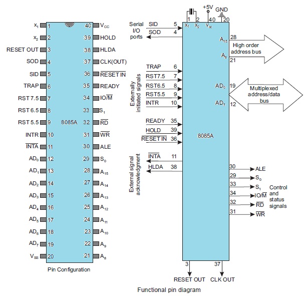
Explanation of Pin Groups
-
Address Bus (A8-A15): The upper 8-bits of the 16-bit address bus used for addressing memory and I/O devices.
-
Multiplexed Address/Data Bus (AD0-AD7): These pins serve two functions:
- During the first clock state (T1), they carry the lower 8-bits of the address.
- During subsequent clock states, they serve as the data bus for data transfer.
-
Control and Status Signals
- ALE (Address Latch Enable): Indicates that the AD0-AD7 lines contain a valid address.
- RD (Read): Indicates a read operation from memory or I/O.
- WR (Write): Indicates a write operation to memory or I/O.
- IO/M (IO/Memory Select): Distinguishes between memory (IO/M = 0) and I/O (IO/M = 1) operations.
- S0, S1 (Status signals): These, along with IO/M, indicate the type of machine cycle (opcode fetch, memory read, I/O write, etc.).
-
Power Supply and Clock
- VCC: +5V power supply.
- VSS: Ground (0V).
- X1, X2: Connections for a crystal or external clock source to drive the internal clock generator.
- CLK (OUT): Clock output signal for synchronizing external devices.
-
Interrupts
- TRAP: Highest priority non-maskable interrupt.
- RST 7.5, RST 6.5, RST 5.5: Maskable interrupts with decreasing priority.
- INTR: General maskable interrupt.
- INTA: Interrupt acknowledge signal sent by the 8085.
-
Serial I/O
- SID (Serial Input Data): Input line for serial data.
- SOD (Serial Output Data): Output line for serial data.
-
Reset
- RESET IN: When low, resets the microprocessor, clearing the program counter and registers.
- RESET OUT: Indicates that the microprocessor is being reset.
-
DMA (Direct Memory Access)
- HOLD: Input from a DMA device to request control of buses.
- HLDA: Acknowledge signal, indicating the 8085 has relinquished control of buses.
Power Supply, Clock & Reset Pins
Let's delve into the power supply, clock, and reset aspects of the 8085 microprocessor, along with a discussion on common 8085 modules:
Power Supply
- Vcc: The 8085 requires a +5V DC power supply. It is crucial to supply a regulated, stable 5V for reliable operation.
- Vss: This is the ground reference (0V) for the power supply.
- Current Requirements: Make sure the power supply can handle the current draw of the 8085 as well as other components in your system.
Clock
- X1, X2: These pins connect to an external crystal oscillator circuit. The crystal's resonant frequency determines the fundamental clock speed of the 8085.
- Frequency: The 8085 supports frequencies up to 3 MHz or 6 MHz (depending on the specific version). You need to choose a crystal with double the desired operating frequency due to the internal clock divider.
- CLK (OUT): This signal is an output from the 8085 with the same frequency as its internal clock. It can serve as a system clock for synchronizing other devices.
Reset
- RESET IN: This active-low signal is used to reset the 8085. When asserted:
- The program counter is set to 0000H.
- Interrupts are disabled.
- Registers are cleared.
- RESET OUT: This active-high output signal can be used to reset other devices in the system during a microprocessor reset.
Control and Status Signal Pins
Control Signals
These are signals generated by the 8085 microprocessor to direct and synchronize operations with memory and I/O devices. Key control signals include:
-
RD (Read):
- Active Low (asserted when the signal is low)
- Issued by the 8085 to indicate that data should be placed on the data bus by the selected memory or I/O device.
- Signals that the microprocessor is reading data.
-
WR (Write):
- Active Low
- Issued by the 8085 to indicate that data on the data bus should be stored into the selected memory location or I/O port.
- Signals that the microprocessor is writing data.
-
IO/M (Input/Output or Memory):
- Used to distinguish between memory and I/O operations.
- IO/M = 1: Indicates the address bus holds an I/O device address.
- IO/M = 0: Indicates the address bus holds a memory address.
-
ALE (Address Latch Enable):
- Active high pulse generated at the beginning of a machine cycle.
- Used to signal external devices to latch the lower 8-bits of the address (AD0-AD7) which are multiplexed with the data bus. This allows the address to remain stable for use by memory and I/O devices.
Status Signals
These signals are provided by the 8085 to reflect its current operational state. Here are the main status signals:
-
S0, S1:
-
These signals indicate the type of operation the 8085 is currently performing:
S1 S0 Operation 0 0 HALT 0 1 Write 1 0 Read 1 1 Opcode Fetch Table: Status Signals
-
How Control and Status Signals Work Together
A simplified interaction using these signals would look like this:
- Address Output: The 8085 places a 16-bit address on the address bus and sends a pulse on ALE to latch the lower order address bits.
- IO/M Signal: The 8085 sets the IO/M line to indicate whether it's a memory or I/O operation.
- Read or Write:
- Read: The 8085 asserts the RD line (sets it low). The addressed device places data on the data bus for the microprocessor to read.
- Write: The 8085 asserts the WR line (sets it low). Data on the data bus is written to the addressed location.
- Status: The 8085 updates S0 and S1 to indicate the type of operation that was just performed.
Role of ALE signal in Demultiplexing
What is the ALE Signal?
- The ALE signal is a control signal generated by the 8085 microprocessor.
- It is a positive-going pulse that occurs during the first clock cycle (T1 state) of each machine cycle.
Purpose of the ALE Signal
The primary function of the ALE signal is to demultiplex the lower-order address/data bus (AD0-AD7). This bus is shared (multiplexed) to carry both:
- Lower 8-bits of the Address (during T1 state): The 8085 needs to send out the 16-bit address of a memory location or I/O port. The lower 8 bits of the address are carried on lines AD0-AD7.
- Data (during subsequent states): The same lines are used to transmit or receive actual data to/from the memory or I/O device.
How ALE Demultiplexes the Bus
-
T1 State:
- The ALE signal goes high.
- The 8085 places the lower 8 bits of the address on lines AD0-AD7.
- An external latch (usually an 8282 or 8283 octal latch) connected to these lines "latches" or captures this address information.
-
Subsequent States (T2, T3, ...):
- ALE goes low.
- The lower-order address lines (AD0-AD7) are now free to be used as a data bus for transferring data.
Diagram
A simple timing diagram can help visualize this:
          ______         ______
ALE      |      |_______|      |______
          _____           _____
AD0-AD7  |Addr |_______| Data |________
         (T1)      (T2, T3, ...)
Key Points:
- The ALE signal is crucial for the 8085 to correctly interface with memory and I/O devices.
- The external latch holds the lower order address bits, freeing the 8085 to continue its fetch or write operation.
Interrupt Pins
What are Interrupts?
Interrupts are mechanisms that allow an external device or an internal event to temporarily halt the currently running program and transfer control to a special routine called the Interrupt Service Routine (ISR). ISRs are designed to handle specific events, providing a way to respond to situations without continuously polling for them.
Types of Interrupts in 8085
The 8085 supports two classes of interrupts:
-
Hardware Interrupts:
- Initiated by signals on dedicated interrupt pins of the 8085.
- Maskable: Can be selectively enabled or disabled using software instructions.
- The 8085 has five hardware interrupts:
- TRAP (RST 4.5): Highest priority, non-maskable (cannot be disabled). Typically used for critical events like power failures.
- RST 7.5: Edge-triggered (responds to a signal transition). Maskable.
- RST 6.5, RST 5.5: Level-triggered (responds to a high or low level on the pin). Maskable.
- INTR: General-purpose interrupt. Non-vectored, which means the requesting device needs to provide the ISR address. Maskable.
-
Software Interrupts:
- Embedded directly into the program using the RST instructions (RST 0 through RST 7).
- These are essentially subroutine calls triggered by software instead of hardware.
- Non-maskable (always execute).
Interrupt Handling Process
Here's a general outline of how the 8085 handles interrupts:
- Interrupt Request: A device asserts its interrupt pin (or an RST instruction is executed).
- Acknowledgement: If interrupts are enabled (using the EI instruction), the 8085 finishes its current instruction and sends an interrupt acknowledge signal (INTA).
- ISR Execution:
- Vectored Interrupts (TRAP, RST 7.5, 6.5, 5.5): The 8085 automatically jumps to a predefined memory location (vector address) associated with the interrupt.
- Non-Vectored Interrupt (INTR): The interrupting device must provide the starting address of its ISR.
- Saving State: The 8085 pushes the current Program Counter (PC) onto the stack to preserve the return address.
- Executing ISR: The ISR code is executed to handle the specific event.
- Return: Upon completion of the ISR, the RET instruction is used to pop the saved PC from the stack, resuming the main program.
Key Points
- Interrupt Masking: The SIM instruction allows you to selectively enable or disable maskable interrupts (RST 7.5, 6.5, 5.5).
- Interrupt Priority: If multiple interrupts occur simultaneously, they are handled according to fixed priority (TRAP has the highest priority).
- ISR Placement: You must carefully place the ISRs in memory, especially for vectored interrupts.
Serial Communication Pins
The 8085 microprocessor doesn't have a dedicated built-in UART for serial communication. However, its software can be used to implement serial communication through its regular input/output pins. Let's explore this in detail:
Serial I/O on the 8085
The 8085 has two pins dedicated to software-implemented serial communication:
- SID (Serial Input Data): Used to receive serial data into the microprocessor.
- SOD (Serial Output Data): Used to transmit serial data from the microprocessor.
How Serial Communication Works
Serial communication involves sending or receiving one bit of data at a time over a single wire. Here's how the 8085 can achieve this:
-
Bit Manipulation: Software instructions are used to set or read the voltage level of the SID and SOD pins individually, allowing you to transmit and receive bits.
-
Timing: Precise timing is crucial in serial communication to ensure the receiver correctly interprets transmitted bits. This usually involves using delay loops or timers in your 8085 code to generate specific intervals.
-
Protocol: Serial communication follows standards such as RS-232. This means adhering to:
- Baud Rate: The speed of transmission (bits per second). Sender and receiver must agree on a common baud rate.
- Start/Stop bits: Special bits to signal the beginning and end of a byte transmission.
- Parity (optional): An error-checking bit.
RIM and SIM Instructions
The 8085 has two special instructions to help in serial communication:
-
RIM (Read Interrupt Mask):
- Allows checking the status of various interrupt flags including status bits for serial data.
- The Serial Input Data (SID) pin's status can be read using this instruction.
-
SIM (Set Interrupt Mask):
- Used to enable/disable interrupts and also sets the SOD pin's status.
- Setting the SOD bit allows you to transmit data using the SOD pin.
Example
A common use case is to implement a simple serial communication program to send and receive characters to or from a computer terminal. Your code would typically involve:
- Initialization: Setting up baud rate, parity, etc., using SIM and RIM.
- Sending Data:
- Using SIM to set the SOD bit corresponding to the bit you want to send.
- Introducing an appropriate delay for the required baud rate.
- Repeat for all bits of the character including start/stop bits.
- Receiving Data:
- Sampling the SID pin using RIM at regular intervals matching the baud rate.
- Assembling bits into a byte.
Limitations
- Speed: Software-based serial communication on the 8085 is relatively slow and limited by your timing precision.
- CPU Overhead: Handling serial communication through software uses up a significant amount of the 8085's processing time.
DMA Pins
The 8085 microprocessor has the HOLD and HLDA pins, and these signals are essential for facilitating a limited form of DMA-like behavior. Here's how it works:
How the 8085 Can Mimic DMA Operations
-
DMA Request: An external peripheral or device (acting as a DMA controller of sorts) asserts the HOLD signal, signaling to the 8085 that it wants to take control of the address and data bus.
-
CPU Acknowledgement At the end of its current machine cycle, the 8085 will respond by:
- Completing any outstanding bus operations.
- Placing its buses in a high-impedance (tri-stated) mode, effectively disconnecting itself from those buses.
- Asserting the HLDA (Hold Acknowledge) signal, indicating it has relinquished control.
-
Peripheral Takes Over: The requesting peripheral takes control of the address and data buses. It can now perform memory read or write operations directly, transferring data without further involvement of the 8085 CPU.
-
Releasing Control: Once the peripheral is done with the data transfer, it releases the HOLD signal.
-
CPU Regains Control: The 8085 detects that HOLD is de-asserted and subsequently takes back control of the buses, resuming its previous operations.
Important Considerations
-
Not True DMA: This isn't true DMA in the strictest sense since it lacks a fully dedicated DMA controller with its own registers and transfer logic. The 8085 CPU is still somewhat involved in the process.
-
Limited Speed: The CPU needs to actively respond to HOLD and HLDA signals, adding some latency and limiting how efficiently large blocks of data can be transferred compared to a system with a full-fledged DMA controller.
-
Synchronization: You need careful synchronization between the 8085 and the peripheral to ensure they don't clash while attempting to access the buses.
Use Cases
Even with its limitations, this technique can be useful for devices that need to transfer data in bursts, like disk drives or high-speed I/O devices.
Example
Imagine an external device that needs to quickly transfer a block of data into the 8085's memory. Using the HOLD/HLDA mechanism, this device can efficiently transfer the data without the CPU needing to actively read in each individual byte.
Block Diagram of 8085
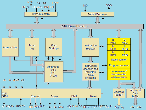
Key Components and their Functions
-
Accumulator: An 8-bit register that's central to arithmetic and logical operations performed by the ALU.
-
Arithmetic and Logic Unit (ALU): Performs arithmetic operations (addition, subtraction, etc.) and logical operations (AND, OR, NOT, etc.). It sets flags (Carry, Zero, Sign, etc.) based on the results.
-
Temporary Register: A temporary holding location for data used during instruction execution.
-
Instruction Register: Holds the currently fetched instruction.
-
Instruction Decoder and Machine Cycle Encoder: Decodes the instruction in the instruction register and generates control signals to coordinate the microprocessor's actions during a machine cycle.
-
Register Array: Contains six general purpose 8-bit registers (B, C, D, E, H, and L), which can be used individually or in pairs (BC, DE, HL) for 16-bit operations.
-
Program Counter (PC): A 16-bit register that holds the memory address of the next instruction to be fetched.
-
Stack Pointer (SP): A 16-bit register pointing to the top of the stack in memory. The stack is used for storing return addresses of subroutines and temporarily storing data.
-
Timing and Control Unit: Generates timing and control signals for all operations within the microprocessor and synchronizes with external devices.
-
Interrupt Control: Handles incoming interrupt requests (if any), acknowledging them and allowing them to temporarily disrupt the current program execution.
-
Serial I/O Control: Facilitates serial input and output, useful for slower communication with certain types of peripherals.
-
Address Bus (A8 - A15): The upper 8-bits of the 16-bit address bus, used to send the most significant portion of an address.
-
Address/Data Bus (AD0 - AD7): A multiplexed bus. It carries the lower 8 bits of an address during the beginning of a machine cycle and data during data transfer operations.
How it Works (Simplified)
- Fetch: The PC provides an address; the instruction is fetched from memory and placed into the Instruction Register.
- Decode: The Instruction Decoder decodes the instruction to understand what needs to be done.
- Execute: The Control Unit generates signals to coordinate the ALU, registers, and other components as they perform the necessary operations.
- Repeat: The process continues, fetching and executing instructions sequentially.
Arithmetic & Logic Unit (ALU) and Timing & Control Unit (CU)
Arithmetic and Logic Unit (ALU)
-
The Heart of Calculations: The ALU is responsible for performing all the arithmetic and logical operations within the 8085.
-
Operations: The 8085's ALU supports the following:
- Arithmetic: Addition, subtraction, increment, decrement
- Logical: AND, OR, XOR, NOT, comparison
- Rotate/Shift: For bit manipulation.
-
Inputs and Outputs:
- Inputs: The ALU typically takes two 8-bit operands as inputs. One operand usually comes from a temporary register, while the other comes from the Accumulator (a special register) or directly from the instruction itself.
- Output: The result of the operation is stored back into the Accumulator.
-
Flags: The ALU sets or clears various flags in the Flag Register based on the result of the operation:
- Carry Flag (CY)
- Zero Flag (Z)
- Sign Flag (S)
- Parity Flag (P)
- Auxiliary Carry Flag (AC)
Timing and Control Unit
-
Conductor of the Orchestra: The Timing and Control Unit is responsible for synchronizing all the operations within the 8085. It ensures the correct sequencing of steps for instruction execution and communication with other system elements.
-
Key Functions:
- Control signal generation: Generates control signals (like RD, WR, IO/M) for internal components, memory, and I/O devices. These signals dictate the direction and timing of data flow.
- Timing Signals: Creates clock and timing signals for the synchronization of the entire system.
- Instruction Execution Coordination: Governs the fetch, decode, and execution stages of instruction processing.
- Interrupt Handling: Acknowledges and manages the priority of interrupts.
-
Internal Components:
- Oscillator: Generates the fundamental clock signal used as a timing reference.
- Control Sequencer: Logic responsible for producing the correct sequence of control signals based on the instructions being executed.
Relationship Between ALU and Timing and Control Unit
The Timing and Control Unit is the mastermind behind the entire operation of the 8085. It issues control signals that direct the ALU to perform specific operations at the appropriate time during instruction execution. The ALU executes the operations, and its resulting flags provide information to the Timing and Control Unit, influencing the flow and decision-making during instruction processing.
Registers
1. Accumulator (A)
- The Workhorse: The 8-bit Accumulator is the most heavily used register in the 8085. It's involved in a vast majority of arithmetic, logical, and I/O operations.
- Arithmetic and Logic: One of the input operands for the ALU typically comes from the Accumulator, and the result of operations is also stored back into it.
- I/O: Data transferred during input and output operations passes through the Accumulator.
2. Temporary Register (T)
- Hidden Helper: The Temporary Register is also an 8-bit register, but it's not directly accessible to the programmer through instructions.
- ALU Support: It serves as a temporary holding space for the second operand during some ALU operations.
- Indirect Addressing: The Temporary Register is sometimes involved in memory operations where the memory address is specified by a register pair (like HL).
3. Program Counter (PC)
- Keeps Track of Execution: The PC is a 16-bit register that holds the memory address of the next instruction to be fetched and executed by the 8085.
- Automatic Incrementing: After fetching an instruction, the PC automatically increments to point to the next sequential instruction in memory.
- Control Flow Changes: Instructions like JUMP and CALL modify the Program Counter to change the execution flow of your program.
4. Stack Pointer (SP)
- LIFO Structure: The Stack Pointer is a 16-bit register that points to the current top of the stack in memory. The stack is a Last-In, First-Out data structure.
- PUSH and POP: Instructions like PUSH and POP add data to or remove data from the top of the stack respectively, with the SP automatically adjusting.
- Subroutine Calls and Interrupts: The stack is used to temporarily store the return address during subroutine calls (CALL) and during interrupt handling. This ensures the program can return to the correct place when the subroutine or interrupt service routine finishes.
5. Register Array (B, C, D, E, H, L)
- General Purpose Registers: These are six 8-bit registers that can be used individually or in pairs:
- BC (16-bit)
- DE (16-bit)
- HL (16-bit)
- Data Storage: Used to temporarily hold data during program execution.
- Memory Addressing: The HL register pair, in particular, is often used to hold 16-bit memory addresses for addressing data in memory.
Key Points
- Limited Registers: The 8085 has a limited set of registers, so programmers need to manage register use efficiently.
- Special Roles: Registers like the Accumulator, Stack Pointer, and Program Counter have very specific roles, while the other general-purpose registers provide more flexibility.
Instruction Register, Instruction Decoder, and Machine Cycle Encoder
1. Instruction Register (IR)
- Purpose: The Instruction Register serves as a temporary holding area for the current instruction being executed by the 8085.
- Operation: When an instruction is fetched from memory, it is placed into the Instruction Register.
- Connection: The IR is directly connected to the internal data bus of the 8085.
2. Instruction Decoder
- Purpose: The Instruction Decoder is a complex combinatorial circuit that analyzes the instruction currently in the Instruction Register. Its main function is to determine the nature of the instruction and figure out what actions the 8085 needs to take to execute it.
- Decoding Process:
- Breaks down the instruction's opcode (the part that specifies the operation).
- Identifies any operands or addressing modes involved.
- Generates internal control signals to orchestrate the various steps required to execute the specific instruction.
3. Machine Cycle Encoder
- Purpose: The Machine Cycle Encoder is responsible for generating the timing and control signals necessary to carry out the steps required for instruction execution.
- Machine Cycles: Instructions in the 8085 consist of one or more machine cycles. Examples include:
- Opcode Fetch cycle: To retrieve the instruction from memory.
- Memory Read cycle: To read data from memory
- Memory Write cycle: To write data to memory
- I/O Read/Write cycles: To communicate with input/output devices
- Control Signals: The Machine Cycle Encoder produces control signals to direct the flow of data, activate specific registers or the ALU, and interface with the memory and I/O systems.
How They Work Together
- Fetch: The opcode of an instruction is fetched from memory and placed into the Instruction Register.
- Decode: The Instruction Decoder analyzes the opcode, figuring out what operation needs to be performed and any data locations involved.
- Execute: The Machine Cycle Encoder generates the necessary sequence of control signals to carry out the instruction, potentially over multiple machine cycles. These signals direct the actions of the 8085's internal components.
The Flag Register
The Flag register in the 8085 is an 8-bit register, with only 5 bits actively used as flags. These flags act as individual flip-flops that are set (1) or reset (0) to reflect specific conditions arising from arithmetic, logical, and other operations performed by the ALU (Arithmetic and Logic Unit).
The 5 Flags:
-
Sign Flag (S):
- Set (1) if the result of an operation is negative (the Most Significant Bit, or MSB, of the result is 1).
- Reset (0) if the result is positive.
-
Zero Flag (Z):
- Set (1) if the result of an operation is zero.
- Reset (0) if the result is not zero.
-
Auxiliary Carry Flag (AC):
- Set (1) if there is a carry-out from the lower nibble (lower 4 bits) into the upper nibble (upper 4 bits) of a result.
- Used primarily in instructions that perform decimal arithmetic.
-
Parity Flag (P):
- Set (1) if the result has even parity (contains an even number of 1s).
- Reset (0) if the result has odd parity.
-
Carry Flag (CY):
- Set (1) if there is a carry-out from the most significant bit (MSB) of a result during addition, or a borrow during subtraction.
- Reset (0) otherwise.
How the Flags are Used:
- Conditional Jumps: Instructions like JZ (Jump if Zero), JNZ (Jump if Not Zero), JC (Jump if Carry), etc. use the status of these flags to determine whether to branch to different parts of the program.
- Decision Making: The processor can examine flag states to modify calculations or behaviors based on previous operations.
Example:
Assembly
Bus Organization
A bus, in a microprocessor system, is a collection of signal lines used to transfer data between the CPU and other components (memory, I/O devices). The 8085 microprocessor has a well-defined bus organization consisting of three main buses:
- Address Bus
- Unidirectional (data flows from the microprocessor outwards)
- 16-bit wide (Can address up to 64KB of memory)
- Carries the memory address of the location the microprocessor wants to access.
- Data Bus
- Bidirectional (data can flow in both directions)
- 8-bit wide (carries 8 bits of data at a time)
- Used to transfer both data and instructions between the microprocessor and memory/IO.
- Control Bus
- Mixture of unidirectional and bidirectional lines
- Consists of various control signals like:
- RD (Read): Indicates the CPU wants to read data from memory or an I/O port.
- WR (Write): Indicates the CPU wants to write data to memory or an I/O port.
- IO/M: Distinguishes between a memory operation (IO/M = 0) or I/O operation (IO/M = 1).
Simplified Diagram
goat
Explanation
- Microprocessor: The 8085 is the heart of the system, initiating and controlling data transfers.
- Address Bus : Used by the microprocessor to specify the location in memory or I/O it wants to communicate with.
- Data Bus: The actual data or instructions are transferred over the data bus.
- Control Bus: The microprocessor uses the control bus to send signals that coordinate the timing and direction of data transfers.
Key Points
- Multiplexing: The 8085 multiplexes the lower 8-bits of the address bus (AD0-AD7) with the data bus (D0-D7) to reduce pin count. This means the same set of lines carries both address bits (at the beginning of a cycle) and data.
- Interfacing: The bus organization dictates how you connect and control memory chips and I/O devices within an 8085-based system.
Working of the 8085
Memory Interfacing
Key Concepts
- Address Bus: The 8085 has a 16-bit address bus (A0-A15), allowing it to address up to 64KB of memory.
- Data Bus: The 8085 has an 8-bit data bus (D0-D7) for transferring data between the microprocessor and memory.
- Control Signals: Control signals (like RD, WR, IO/M) are crucial for indicating the direction of data flow and the type of operation.
Memory Organization
- Memory Map: The 64KB address space of the 8085 is often divided into portions for specific purposes:
- ROM (Read-Only Memory): Used to store the program instructions, which usually reside at the lower end of the address space.
- RAM (Random Access Memory): Used for storing variables, temporary data, and the stack, which often starts at the higher end of the address space.
- I/O Mapped I/O: Some address space can be reserved for interfacing with input/output devices.
Memory Read Cycle
- Address Output: The 8085 places the 16-bit address of the memory location it wants to read on the address bus.
- Control Signals:
- The IO/M signal is set low (IO/M = 0), indicating a memory operation.
- The RD (Read) signal is asserted (set low) to signal a read operation.
- Data Transfer: The addressed memory chip places the data from the specified location onto the data bus.
- Data Latch: The 8085 microprocessor reads the data from the data bus and stores it internally (likely in a register).
Memory Write Cycle
- Address Output: Similar to a read cycle, the 8085 places the 16-bit memory address on the address bus.
- Data Output: The 8085 places the data it intends to write onto the data bus.
- Control Signals:
- IO/M is set low (IO/M = 0) to indicate a memory operation.
- The WR (Write) signal is asserted (set low) to signal a write operation.
- Data Storage: The addressed memory location stores the data from the data bus.
Memory Interfacing Techniques
-
Address Decoding: To interface multiple memory (and I/O) devices, you'll need address decoding logic. Using gates and logic circuits, you can ensure that the correct memory chip or I/O device is activated based on the address on the address bus.
-
Multiplexing: The lower 8-bits of the address bus (A0-A7) are multiplexed with the data bus (D0-D7). The ALE signal is used to latch the address and demultiplex it.
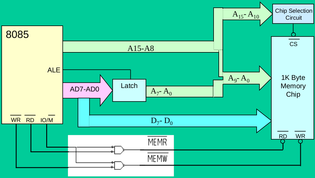
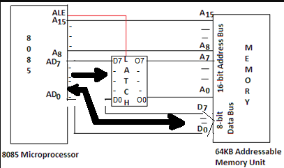
Demultiplexing of Lower Order Address Bus & Data Bus
Why Demultiplexing is Needed
The Intel 8085 utilizes a multiplexed address/data bus to reduce the number of pins required. The lower 8 lines (AD0-AD7) carry two types of information:
-
Address (during T1 state): During the first clock cycle of a machine cycle, these lines hold the lower 8 bits of a 16-bit memory or I/O address.
-
Data (during subsequent states): In the remaining clock cycles, those same lines transmit or receive the actual data being sent to or from a memory location or I/O device.
Demultiplexing Process
Demultiplexing is the process of separating the address and data information so the 8085 and external devices can operate correctly. Here's how it's achieved:
-
The ALE Signal: During the first clock cycle (T1), the 8085 asserts the ALE (Address Latch Enable) control signal. This signal goes high.
-
External Latch: An external latch circuit (e.g., 8282 or 74LS373 octal latch) is connected to the AD0-AD7 lines. When the ALE signal goes high, this latch captures and holds the lower 8 bits of the address.
-
Address Decoded: The latched lower-order address bits, along with the higher-order address bits (A8-A15), provide the complete 16-bit address for memory or I/O devices.
-
Data Bus Freed: After the T1 state, the ALE signal goes low. The AD0-AD7 lines are now free to be used as a data bus for the remainder of the machine cycle.
Diagram
Key Points
- Demultiplexing enables the 8085 to interface with memory and I/O devices correctly by separating the address and data functions of the same physical bus lines.
- The ALE signal plays a crucial role in timing the latching of address information.
Instruction Fetching, Decoding and Execution
Instruction Fetching
- Program Counter (PC): The PC, a 16-bit register, holds the memory address of the next instruction to be fetched.
- Memory Address Register (MAR): The contents of the PC are copied into the MAR.
- Memory Read: The 8085's control unit sends a read signal to the memory, and the instruction code at the address specified by the MAR is placed on the data bus.
- Instruction Register (IR): The instruction code is transferred from the data bus to the Instruction Register.
- PC Increment: The PC is incremented to point to the next instruction in memory.
Instruction Decoding
- Instruction Decoder: The instruction code in the IR is interpreted by the 8085's instruction decoder circuitry. It identifies the specific operation to be performed (opcode) and the operands involved.
- Control Signals: The instruction decoder generates appropriate control signals to coordinate the upcoming execution. These signals control the flow of data within the 8085, directing the ALU, registers, and the timing of operations.
Instruction Execution
The execution phase varies significantly depending on the specific instruction. Here's a general breakdown of the kinds of steps involved:
- Operand Fetching: If the instruction uses operands (data), additional machine cycles may be involved in fetching these from either:
- Registers: Accessed directly within the microprocessor.
- Memory: The MAR is loaded with the memory address of the operand, and another memory read operation is performed.
- ALU Operations: For arithmetic or logical instructions, the ALU is engaged to perform the required calculation or comparison.
- Result Storage: The results of an operation may be stored in:
- Accumulator: A special register within the 8085.
- Other General-Purpose Registers
- Memory: Another memory write operation might be needed.
- Update Status Flags: The ALU sets flags (Zero, Carry, Sign, etc.) to reflect the results of its operations, which can be used for conditional branching later.
Example: ADD B Instruction
Let's assume the instruction "ADD B" (add the value in register B to the accumulator) is being executed:
- Fetch: The opcode for ADD B is fetched from memory and placed in the IR.
- Decode: The instruction decoder determines that this is an addition operation and that the operand is in register B.
- Execute:
- The contents of register B are fetched.
- The ALU performs the addition between the accumulator's current value and the value from register B.
- The result is stored back into the accumulator.
Microprocessor vs. Microcontroller
Core Distinction
- Microprocessor: A Central Processing Unit (CPU) on a chip. It's the "brain" of a computer system, designed for general-purpose computing and requires external components to form a functional system.
- Microcontroller: A self-contained "computer-on-a-chip." It integrates a CPU, memory, and peripherals, optimized for embedded control applications.
Key Features
| Feature | Microprocessor | Microcontroller |
|---|---|---|
| System Design | Core of a complex system | Often the entire system |
| Complexity | Less complex internally | More complex internally due to integrated components |
| Instruction Set | Larger, versatile instruction set for diverse operations | Smaller, tailored instruction set for specific applications |
| Memory | External RAM, ROM, flash required | On-chip RAM, ROM, often with flash memory |
| Peripherals | Requires external interfacing | Built-in peripherals (timers, ADCs, DACs, communication ports) |
| Power Consumption | Generally higher power consumption | Optimized for low power operation |
| Cost | Generally lower cost | Can be higher due to integrated components |
| Flexibility | Highly flexible for various tasks | More specialized, less adaptable to diverse use cases |
| Applications | Desktop computers, laptops, servers, complex systems | Embedded systems, appliances, medical devices, IoT devices |
| Examples | Intel Core Series, AMD Ryzen, IBM Power | Atmel AVR, PIC, ARM Cortex-M, Texas Instruments MSP430 |
Table: Microprocessor vs. Microcontroller
Additional Considerations
- Programming: Microcontrollers often require more low-level knowledge of hardware for efficient programming.
- Performance: Microprocessors generally excel in raw computational performance, while microcontrollers prioritize power efficiency and responsiveness.
- Bit Handling: Microcontrollers frequently offer better support for bit-level operations on I/O pins.
Illustrative Analogy
Imagine building a custom robot:
- Microprocessor: Like buying the high-performance brain for your robot. You'd still need to buy sensors, motors, a power supply, and design the entire body.
- Microcontroller: Like buying a pre-assembled robot kit with a basic brain, sensors, and motors. You focus on programming behavior, potentially adding some external components if needed.
When to Choose Which
- Microprocessor: Need high computational power, flexibility for a variety of tasks, or working with large amounts of data.
- Microcontroller: Self-contained solution, low-power, real-time control, or cost-sensitive applications are priorities.