Unit-2. Electrostatics - Medium Solutions
Part A: Definitions (1-2 marks)
Electric Field (E)
Definition: Electric field at a point is the force experienced by a unit positive charge placed at that point.
Mathematical Form:
E = F/q₀
E = kQ/r² (for point charge)
Units: N/C or V/m
Properties:
- Vector quantity (has magnitude and direction)
- Direction: Away from +ve charge, towards -ve charge
- Exists around any charge
 Figure: Electric field lines around charges
Electric Potential (V)
Definition: Electric potential at a point is the work done in bringing a unit positive charge from infinity to that point against the electric field.
Formula:
V = W/q = kQ/r
Unit: Volt (V) = Joule/Coulomb (J/C)
Key Points:
- Scalar quantity (no direction)
- Reference point: V = 0 at infinity
- V decreases as distance increases
- V is positive around +ve charge, negative around -ve charge
Electric Potential Difference (ΔV)
Definition: Work done in moving a unit positive charge from one point to another in an electric field.
Formula:
ΔV = V₂ - V₁ = W/q
W = q(V₂ - V₁)
Unit: Volt (V)
Physical Meaning:
- Measures energy required to move charge
- Battery provides potential difference
- Higher ΔV → More energy available
Electric Flux (Φ)
Definition: Electric flux through a surface is the total number of electric field lines passing through that surface.
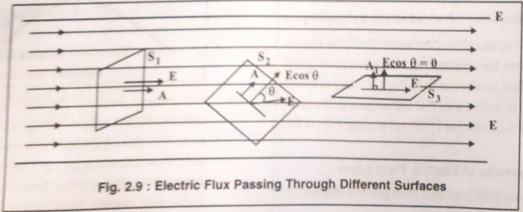 Figure: Electric flux through a surface
Formula:
Φ = E · A = EA cos θ
Where:
- E = Electric field
- A = Area of surface
- θ = Angle between E and normal to surface
Unit: N·m²/C or V·m
Maximum flux: When θ = 0° (field perpendicular to surface) Zero flux: When θ = 90° (field parallel to surface)
Capacitor
Definition: A device consisting of two conductors (plates) separated by an insulator (dielectric), used to store electric charge and energy.
Basic Structure:
- Two parallel conducting plates
- Separated by dielectric material (air, mica, ceramic)
- One plate holds +Q, other holds -Q
Function: Stores electrical energy in the electric field between plates
Capacitance (C)
Definition: Capacitance is the ability of a conductor or capacitor to store electric charge. It's the ratio of charge stored to potential difference.
Formula:
C = Q/V

For parallel plate:
C = ε₀εᵣA/d = ε₀KA/d
Where:
- ε₀ = 8.85×10⁻¹² F/m (permittivity of free space)
- εᵣ = K = dielectric constant
- A = area of plates
- d = distance between plates
Unit: Farad (F)
- 1 Farad = 1 Coulomb/Volt
- Practical units: μF (10⁻⁶ F), nF (10⁻⁹ F), pF (10⁻¹² F)
Part B: Detailed Answers (2-3 marks)
(1) State and explain Coulomb's law
Statement: The force of attraction or repulsion between two stationary point charges is directly proportional to the product of the charges and inversely proportional to the square of the distance between them.
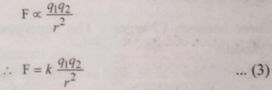 Figure: Force between two point charges
Mathematical Form:
F ∝ q₁q₂  and  F ∝ 1/r²

Therefore: F = k(q₁q₂)/r²
Where:
- k = 9 × 10⁹ N·m²/C² (Coulomb's constant)
- k = 1/(4πε₀)
- ε₀ = 8.85 × 10⁻¹² F/m
Vector Form:
F⃗ = k(q₁q₂/r²) r̂
Nature of Force:
- Like charges (both +ve or both -ve): Repulsive (push apart)
- Unlike charges (+ve and -ve): Attractive (pull together)
Key Points:
- Valid for point charges or spherical charge distributions
- Force acts along the line joining the charges
- Obeys Newton's third law (action-reaction pair)
(2) Draw and explain characteristics of electric field lines
Electric Field Lines: Imaginary lines whose tangent at any point gives the direction of electric field at that point.
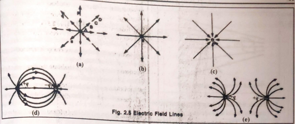 Figure: Electric field line patterns for different charge configurations
Characteristics:
-
Origin and Termination:
- Start from positive charges (or infinity)
- End at negative charges (or infinity)
-
Direction:
- Tangent to field line gives direction of electric field
- Arrow shows direction of force on +ve test charge
-
No Intersection:
- Two field lines never cross each other
- If they crossed, field would have two directions at that point (impossible)
-
Density indicates strength:
- Closely spaced lines → Strong field
- Widely spaced lines → Weak field
- Number of lines ∝ magnitude of charge
-
Uniform field:
- Parallel and equally spaced lines
- Example: Between two parallel charged plates
-
Imaginary nature:
- Lines are visualization tool, not physical entities
- Electric field is real and exists everywhere
-
Perpendicular to surface:
- Field lines always meet conductor surface perpendicularly
- Tangential component = 0 on conductor surface
-
Open curves:
- Electrostatic field lines never form closed loops
- They have definite starting and ending points
(3) Parallel plate capacitor - construction, capacitance, factors
Construction:
Figure: Structure of parallel plate capacitor
- Two parallel conducting plates of equal area A
- Separated by distance d
- Dielectric material (air, mica, ceramic) between plates
- One plate connected to +ve terminal (charge +Q)
- Other plate connected to -ve terminal (charge -Q)
Capacitance Formula:
C = ε₀εᵣA/d = ε₀KA/d

Where:
ε₀ = 8.85×10⁻¹² F/m
εᵣ = K = relative permittivity (dielectric constant)
A = area of plates (m²)
d = separation between plates (m)
Factors Affecting Capacitance:
-
Area of plates (A):
- C ∝ A
- Larger area → More charge storage → Higher capacitance
-
Distance between plates (d):
- C ∝ 1/d
- Smaller distance → Stronger field → Higher capacitance
-
Dielectric constant (K):
- C ∝ K
- Higher K → More capacitance
- Air: K=1, Mica: K≈6, Ceramic: K≈1000
-
Permittivity of free space (ε₀):
- Fundamental constant = 8.85×10⁻¹² F/m
Applications:
- Tuning circuits, filters, energy storage
- Power supply smoothing, coupling/decoupling
- Flash photography, timing circuits
(4) Series combination of capacitors
Configuration: Capacitors connected end-to-end (negative of one to positive of next)
Figure: Capacitors in series connection
Characteristics:
-
Same charge on all capacitors:
Q₁ = Q₂ = Q₃ = Q (constant) -
Voltage divides:
V = V₁ + V₂ + V₃ -
Individual voltages:
V₁ = Q/C₁, V₂ = Q/C₂, V₃ = Q/C₃
Derivation:
V = V₁ + V₂ + V₃
Q/Cₛ = Q/C₁ + Q/C₂ + Q/C₃

Dividing by Q:
1/Cₛ = 1/C₁ + 1/C₂ + 1/C₃
Special Cases:
Two capacitors: Cₛ = (C₁C₂)/(C₁+C₂)

n equal capacitors: Cₛ = C/n
Key Point: Equivalent capacitance is less than smallest individual capacitance
Application: To reduce effective capacitance and increase voltage rating
(5) Parallel combination of capacitors
Configuration: All capacitors connected to same two points (all +ve terminals together, all -ve terminals together)
Figure: Capacitors in parallel connection
Characteristics:
-
Same voltage across all capacitors:
V₁ = V₂ = V₃ = V (constant) -
Charge divides:
Q = Q₁ + Q₂ + Q₃ -
Individual charges:
Q₁ = C₁V, Q₂ = C₂V, Q₃ = C₃V
Derivation:
Q = Q₁ + Q₂ + Q₃
CₚV = C₁V + C₂V + C₃V

Dividing by V:
Cₚ = C₁ + C₂ + C₃
Special Case:
n equal capacitors: Cₚ = nC
Key Point: Equivalent capacitance is greater than largest individual capacitance
Application: To increase effective capacitance and charge storage
(6) Effect of dielectric on capacitance of capacitor
Dielectric: Insulating material (glass, mica, ceramic, paper) placed between capacitor plates
Figure: Effect of dielectric on capacitor
Effect: Capacitance Increases
C = KC₀

Where:
C₀ = capacitance with air/vacuum
K = dielectric constant (εᵣ)
K > 1 for all materials
Why Capacitance Increases:
-
Polarization: Dielectric molecules align with electric field
- +ve ends toward -ve plate
- -ve ends toward +ve plate
-
Reduced field: Internal field opposes applied field
E = E₀/K -
Reduced voltage: For same charge Q
V = V₀/K -
Increased capacitance: C = Q/V
C = Q/(V₀/K) = K(Q/V₀) = KC₀
Other Effects:
- Increases breakdown voltage: Can apply higher voltage without sparking
- Mechanical support: Keeps plates separated uniformly
- Compact design: Higher C in smaller size
Common Dielectrics:
| Material | K (Dielectric Constant) |
|---|---|
| Vacuum | 1.0000 |
| Air | 1.0006 |
| Paper | 3.7 |
| Glass | 5-10 |
| Mica | 6 |
| Ceramic | 100-1000 |
Part C: Numerical Problems (3 marks)
(1) Force between two charges (Coulomb's law)
Given:
- q₁ = 20 μC = 20 × 10⁻⁶ C
- q₂ = 10 μC = 10 × 10⁻⁶ C
- r = 0.02 m = 2 cm
- k = 9 × 10⁹ N·m²/C²
Formula:
F = kq₁q₂/r²
Calculation:
F = (9×10⁹) × (20×10⁻⁶) × (10×10⁻⁶) / (0.02)²

F = (9×10⁹) × (200×10⁻¹²) / (4×10⁻⁴)

F = 1800×10⁻³ / 4×10⁻⁴

F = 1.8 / (4×10⁻⁴) = 4500 N
Answer: F = 4500 N (repulsive force, both charges positive)
(2) Potential difference from work done
Given:
- W = 1600 J
- q = 25 C
Formula:
V = W/q
Calculation:
V = 1600/25 = 64 V
Answer: V = 64 V
Interpretation: 64 joules of work is required to move 1 coulomb of charge between the two points.
(3) Capacitance from charge and voltage
Given:
- Q = 60 μC = 60 × 10⁻⁶ C
- V = 12 V
Formula:
C = Q/V
Calculation:
C = (60×10⁻⁶)/12 = 5×10⁻⁶ F = 5 μF
Answer: C = 5 μF
(4) Three 10μF capacitors in series and parallel
Given: C₁ = C₂ = C₃ = 10 μF
Series Connection:
For n equal capacitors: Cₛ = C/n

Cₛ = 10/3 = 3.33 μF
Parallel Connection:
For n equal capacitors: Cₚ = nC

Cₚ = 3 × 10 = 30 μF
Answers:
- Series: Cₛ = 3.33 μF
- Parallel: Cₚ = 30 μF
Comparison: Parallel gives 9 times more capacitance than series for same capacitors!
(5) Capacitance of small capacitor
Given:
- A = 10 mm² = 10 × 10⁻⁶ m² = 10⁻⁵ m²
- d = 1 mm = 1 × 10⁻³ m
- ε₀ = 8.85 × 10⁻¹² F/m
- Air dielectric (K = 1)
Formula:
C = ε₀A/d
Calculation:
C = (8.85×10⁻¹²) × (10⁻⁵) / (10⁻³)

C = 8.85×10⁻¹⁷ / 10⁻³

C = 8.85×10⁻¹⁴ F = 0.0885 pF
Answer: C = 8.85 × 10⁻¹⁴ F (or 0.0885 pF)
Note: Very small capacitance due to small area!
(6) Area required for 1 Farad capacitor
Given:
- C = 1 F
- d = 1 mm = 10⁻³ m
- ε₀ = 8.85 × 10⁻¹² F/m
Formula:
C = ε₀A/d → A = Cd/ε₀
Calculation:
A = (1) × (10⁻³) / (8.85×10⁻¹²)

A = 10⁻³ / 8.85×10⁻¹²

A = 1.13 × 10⁸ m²
Converting to km²:
A = 1.13 × 10⁸ m² = 113 km²
Answer: A = 1.13 × 10⁸ m² (113 km²)
Interpretation: This shows 1 Farad is an enormous capacitance! That's why we use μF, nF, pF in practice. Area needed is larger than a small city!
(7) Mixed circuit (series-parallel combination)
Problem: Find equivalent capacitance when C₁ and C₂ are in parallel, and this combination is in series with C₃.
Given:
- C₁ = 10 μF
- C₂ = 20 μF
- C₃ = 30 μF
- Configuration: (C₁ ∥ C₂) in series with C₃
Step 1: Parallel combination of C₁ and C₂
C₁₂ = C₁ + C₂ = 10 + 20 = 30 μF
Step 2: Series combination with C₃
1/Cₜ = 1/C₁₂ + 1/C₃

1/Cₜ = 1/30 + 1/30 = 2/30

Cₜ = 30/2 = 15 μF
Answer: Total capacitance = 15 μF
Alternative method (for two equal capacitors in series):
Cₜ = (C₁₂ × C₃)/(C₁₂ + C₃) = (30 × 30)/(30 + 30) = 900/60 = 15 μF
Quick Reference
Essential Formulas
Coulomb's Law: F = kq₁q₂/r²,  k = 9×10⁹ N·m²/C²
Electric Field: E = F/q = kQ/r²
Electric Potential: V = W/q = kQ/r
Potential Difference: ΔV = V₂ - V₁ = W/q
Electric Flux: Φ = EA cos θ
Capacitance: C = Q/V
Parallel Plate: C = ε₀εᵣA/d = ε₀KA/d
Series: 1/Cₛ = 1/C₁ + 1/C₂ + 1/C₃
Parallel: Cₚ = C₁ + C₂ + C₃
Dielectric effect: C = KC₀
Energy stored: U = ½QV = ½CV² = Q²/(2C)
Important Constants
k (Coulomb's constant) = 9 × 10⁹ N·m²/C²
ε₀ (Permittivity of free space) = 8.85 × 10⁻¹² F/m
e (Electron charge) = 1.6 × 10⁻¹⁹ C
1 μF = 10⁻⁶ F
1 nF = 10⁻⁹ F
1 pF = 10⁻¹² F
Medium Solutions - Unit 2